


A mobile phone network is called a Cellular Network since it is made up of a large number of signal areas termed as cells. These cells overlap or join each other to create a large coverage area. Users on the network can cross into different cells without losing connection.
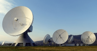
Each cell contains a base station or mobile phone tower, which emits and receives the mobile signals. A mobile device will connect to the closest or least congested base station. The BTS’s are connected to a digital exchange where the communication is transmitted to other telephone or data networks.
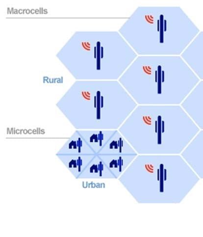
Cells will often be smaller in size throughout large towns and cities due to a large number of users in the area and multitude of physical obstructions present. In villages where are vast open spaces, the cell size is larger. The higher the population density, the more the number of base stations that are needed. Urban areas are generally served by ‘Micro cells’ which have a coverage range of just one kms to 2 kms while Rural areas are generally served by ‘Macro cells’ which have a coverage range of anywhere between 5 kms to 32 kms.
To fill the coverage gaps in areas missed out by Macro and Micro cells we now have ‘Small cells’ which are mainly of two types. ‘Pico cells’ are used in commercial complexes and corporate office buildings and have a coverage range of 100 to 250 metres. ‘Femto cells’ are used in residential areas within homes and have a coverage range similar to a Wi-Fi router between 10 to 50 metres.
Signal Strength and Quality:
The Signal Strength Indicator on your mobile device will offer a very basic idea of the mobile signal amplitude and also the signal quality. Each mobile manufacturer calculates the number of bars to display differently, which results in different readings between phones in the same geographic location. It is important to note that higher number of signal bars do not always imply that you can make a call. Users may sometimes have signal bars but are not able to place a call due to network congestion.
In this case, it becomes important to quantify the signal strength and quality in specific units to get a clear picture of the grade of signal reception on your phone. Below is the list of basic parameters used to describe signal reception and how to interpret them.
1) RSSI:
Applicable to GSM and 3G networks. The exact signal strength, often referred to as Received Signal Strength Indication (RSSI), is measured in dBm. The dBm scale is grossly between -50 and -120dBm, where -50 is a perfect signal and -120 being the point when you lose the network. RSSI is a measure of both the usable signal as well as the noise in a single figure.
- -50 to -75 dBm – High Signal
- -76 to -90 dBm – Medium Signal
- -91 to -100 dBm – Low Signal
- -101db to -120 dBm – Poor Signal
2) RSRP:
Applicable to LTE networks. Reference Signal Received Power (RSRP) is a slightly different scale of measuring signal strength than GSM or 3G networks. This usually has a value around -20dBm lower than RSSI, so -100dBm (RSSI) would be equal to around -120dbm (RSRP). RSRP is a more precise measure of signal strength than RSSI, since it excludes noise and interference on the network, measuring only the usable portion of the signal. It should be kept in mind that just because RSRP signals appear lower, it does not imply that your signal is poor.
- -75dBm and -88dBm is a strong signal
- -89dBm and -96dBm is a very good signal
- -97dBm and -105dBm is good
- -106dBm and -112dBm is fair
- -113dBm and -125dBm is poor
3) SNR:
The “Signal to Noise Ratio” is a measurement which compares the signal strength to the level of background noise. The higher the SNR, the better your signal quality will be. The SNR reading is automatically calculated by the BTS in dB. On the scale of SNR 4 is poor and 25 is great.
4) ASU:
"Arbitrary Strength Unit" is a value which is proportional to your RSRP. The higher the value, the better your signal quality. ASU = RSRP + 140, so say for example you have an RSRP of -100dBm, then your ASU will be 40.
5) RSRQ:
‘Reference Signal Received Quality’ is the ratio of usable signal to noise and interference measured in dBm. RSRQ=RSRP-RSSI.
Factors Affecting Cellular Network Coverage:
Mobile base stations have a set coverage area to which they can broadcast a signal. This distance is dictated by the frequency band used, physical obstructions in the path of propagation, the output power of the BTS and the number of users connected simultaneously. Each of these factors has been detailed below.
1) Frequency band used:
Lower frequency bands have longer wavelengths and travel further in a given terrain compared to higher frequency bands which have shorter wavelengths. To put things in perspective we consider a flat terrain with a tower mounted with a transceiver 60 metres above ground level and no physical obstruction. In this theoretical scenario, 850 MHz will travel 29.4 Km while 1800 MHz will travel 14 kms and 2500 MHz will travel 10 kms.
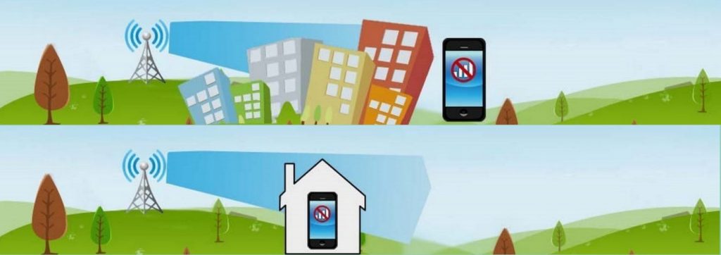
2) Physical obstructions:
One of the most common causes of the poor mobile signal is when the radio waves are degraded by obstacles between the base station and the user. This includes buildings, terrains such as hills, vegetation, weather and other structures. Poor indoor coverage is usually caused by building materials that assist in shielding the signal from entering the building. Brick, concrete and tiles are great at shielding the signal.
3) Output power:
One of the most critical factors in determining signal reach is the towers ‘search window’ area, determined by its output power. In order for the mobile network to work efficiently, the towers need to supply the majority of customers within that cell area with the best quality service and ignore those on the edge that use up valuable resources. They do this by limiting the reach at which a customer’s phone can see the tower. A tower’s search window might typically be set to anywhere between 5 kms to 30 kms, so only users within that range would be able to connect to the tower. If you are in the outer periphery of the coverage area, you may experience unreliable service along with call drops and slow data speeds.
4) Number of users connected:
Believe it or not, the number of users connected simultaneously to the tower can also affect your signal level. During times of peak use, customers may experience lower signal than normal. This is due to an effect called ‘cell breathing’ seen in self-optimising networks, where a tower decreases its coverage area so that distant users can be offloaded to a neighbouring tower. Cell breathing will affect 3G networks, but not LTE networks.
Methods of capacity augmentation:
As the era of the voice-centric network is coming to an end, paving the way for a new age of data-centric network, there has arisen a strong demand for capacity on the network. Users now need uninterrupted access to high-speed data connectivity. Mobile internet which started with GPRS and EDGE, progressing through EvDO and HSPA+ has now reached LTE advanced and Gigabit LTE speeds. To meet this growing demand for high-speed mobile data, newer technologies have come into play. Below are listed the three main methods of capacity augmentation and I have used the analogy of a highway with vehicles to explain them.
1) QAM:
Quadrature Amplitude Modulation or QAM is a form of modulation which is widely used for modulating data signals onto a carrier used for radio communications. QAM is more efficient than other types of data modulation such as PSK, which is why it is used more widely, although various data modulation forms may be deployed simultaneously.
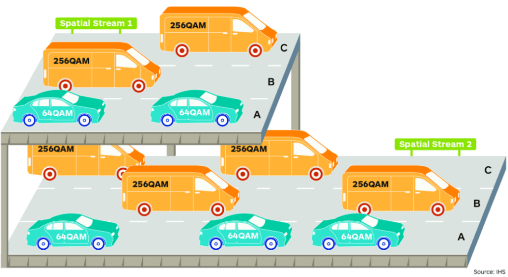
In our analogy (refer image below), the QAM is like the vehicle carrying passengers (bits of data) over the highway. Smaller the value of QAM, lesser the data it can carry and larger the value, more the data which can be carried by it. So 64QAM is like a car which can transport few passengers while 256QAM is like a truck which can transport way more passengers.
2) Carrier aggregation:
A carrier is a chunk of spectrum which is used for transmitting and receiving the data signal. For LTE the individual carrier bandwidth can be 1.4 MHz, 3 MHz, 5 MHz, 10 MHz, 15 MHz or 20 MHz each. For achieving bandwidth greater than 20 MHz we have a method called carrier aggregation which combines individual carriers to form a much wider carrier which can provide higher uplink and downlink speeds than each individual carrier. This can be in the form of intra band aggregation where all carriers belong to the same band like B40-B40 or in the form of inter-band aggregation where individual carriers belong to different bands like B3-B5-B40. Currently, a maximum of 5 carriers can be aggregated to give a resultant of maximum 100 MHz bandwidth by combining five carriers of 20 MHz each.
In our analogy (Refer image above), the individual carriers are like the lanes of a highway. The lanes A/B/C represent the individual carriers within the same band or across multiple frequency bands, and the image represents a 3 carrier aggregation. Greater the number of lanes, widen the highway and subsequently more the number of vehicles which it can carry simultaneously.
3) MIMO:
Multi-input Multi-output or MIMO is a method of capacity augmentation which makes use of multiple sending and receiving antennae at the BTS as well as the user’s mobile device. This method comes in handy when an operator has limited spectrum holding in a single band or has reached the maximum limit of 5 carrier aggregation and wants to further boost capacity. Each transmitting and receiving antenna on the BTS is placed at a slightly different angle thus creating an individual spatial stream of data which will take a somewhat different path to reach the user’s mobile device and connect to its multiple antennae thus multiplying the available bandwidth and speed. 2X2 MIMO has two transmitting and receiving antennae on the BTS connected to 2 transmitting and receiving antennae on the user’s mobile device. Subsequently we have 4X4, 8X8, 16X16, 32X32 and 64X64 MIMO also termed as Massive MIMO.
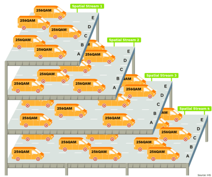
In our analogy (refer image above), when a highway reaches a limitation of the maximum number of lanes which can be added due to presence of houses on both sides of the highway, the only way to increase vehicle carrying capacity is to add new layers of road (spatial data streams) one above another. The 5 lanes A/B/C/D/E represent 5 carrier aggregation while the 4 layers of road (spatial streams 1-4) represent 4X4 MIMO.
Footnote:
The article has been written by me to throw light on some of the basic essentials in cellular communication networks and to simplify telecommunication concepts for beginners. Images used in the article are the sole property of mobilenetworkguide.com.au and technology.ihs.com and have been used for representational purposes only. If you have any questions or opinions, please let us know through the comments section below.